Variant Condition Propagation with Variant Sources and Sinks
How Variant Condition Propagation Works
当你指定变化ant conditions in models containingVariant SourceandVariant Sinkblocks, Simulink®evaluates the variant controls specified on the variant blocks and automatically propagates the variant conditions to the connecting blocks to determine which components of the model are active during simulation. Simulink then deactivates the model components associated with the inactive choices and visualizes the active connections. Simulink uses theVariant activation timeblock parameter to determine the time frame when it chooses the active variant choice. For more information on variant activation time, seeActivate Variant During Different Stages of Simulation and Code Generation Workflow.
Note
The variant condition annotations displayed on model components help you visualize the propagated conditions.
To view the variant condition annotations, on theDebugtab, selectInformation Overlays>Variant Legend.
IfVariant Legendis not available, on theDebugtab, selectInformation Overlays>Variant Conditions.
Cross-Coupling of Inputs and Outputs
In this model, theVariant Sourceblock has two inputs with variant conditionsVar == 1andVar==2, respectively. The first input to theVariant Sourceblock branches into its second input before connecting to the block. The second input with variant conditionVar==2is the default variant choice.

During simulation, this model exhibits three modes of operation:
| Variant Condition | Active Choice |
|---|---|
Var == 1 |
First input of |
Var == 1 || Var == 2 |
Second input ofVariant Sourceand the branch of the first input. |
Var == 2 |
Second input ofVariant Source. |
Cascading Blocks and Compounding Conditions
In this model,Variant Source AandVariant Source Bare twoVariant Sourceblocks, each fed by two input ports, and connected in a cascading manner. The inputs toVariant Source Aare active whenVarA == 1orVarA == 2. The output ofVariant Source Abranches into one of the inputs ofVariant SourceB. The inputs toVariant SourceBare active whenVarB == 1orVarB == 2.

During simulation, this model exhibits eight modes of operation:
| Variant Condition | Active Choice |
|---|---|
VarA == 1 && VarB == 1 |
First inputs of |
VarA == 1 && VarB == 2 |
First input ofVariant Source Aand the second input ofVariant Source B. |
VarA == 2 && VarB == 1 |
Second input ofVariant Source Aand the first input ofVariant Source B. |
VarA == 2 && VarB == 2 |
Second inputs ofVariant Source AandVariant Source B. |
VarA == 1 && VarB != (1,2) |
First input ofVariant Source A. |
VarA == 2 && VarB != (1,2) |
Second input ofVariant Source B. |
VarA != (1,2) && VarB == 1 |
None |
VarA != (1,2) && VarB == 2 |
Second input ofVariant Source B. |
VarA != (1,2) && VarB != (1,2) |
None |
Hierarchical Nesting of Sources or Sinks
In this model, multipleVariant Sourceblocks are used to create hierarchical nesting of variant choices and provides variation on sensor inputs . Multiple choices for sensors are first grouped by series:A Series,B Series, andC Series. TheVariant Sourceblock,设备模型, selects a sensor from one of the series. TheVendorthen chooses amongst the sensor choices provided by设备模型andXSensor.
Simulink propagates complex variant control conditions to determine which model components are active during compilation.

For more information, seeHierarchical Nesting of Variant Sources and Variant Sinks.
Net Variant Condition
The net variant condition is the total of the local condition and its ancestral condition.
In this model,Variant SourceandVariant Source1are two single-input/single-outputVariant Sourceblocks with the variant conditionsV==1andW = = 1, respectively. TheAllow zero active variant controlsparameter is set toonfor both the variant blocks. When this option is selected and there is no active variant choice, Simulink disables all the blocks connected to the input and output stream of theVariant Sourceblock.
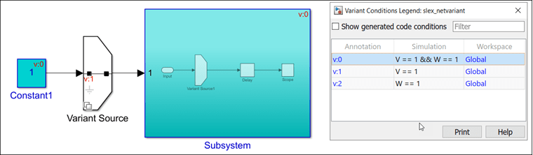
When you simulate this model, theVariant Source1block and other blocks within theSubsystem块接收当地条件W = = 1propagated from theVariant Source1block. The ancestral conditionV==1is propagated from theVariant Sourceblock onto theSubsystemblock. Therefore, the net variant condition on theVariant Source1block and other blocks within theSubsystemblock isV==1 && W==1. If theAllow zero active variant controlsparameter is set toofffor theVariant Sourceblock, then condition on theSubsystemblock isW = = 1.
Condition Propagation with Subsystems
A variant condition can activate or deactivate aSubsystemblock, but variant conditions cannot propagate into the subsystem. ASubsystemblock can propagate variant conditions from its output port if that variant condition originates at a port inside the subsystem.
A subsystem can either be a virtual (grouped or ungrouped) or an atomic subsystem depending on the selections made in its Block Parameters dialog box.
Grouped Virtual: Select theTreat as grouped when propagating variant conditionscheck box. A grouped virtual subsystem has a continuous line.
Ungrouped Virtual: Clear theTreat as grouped when propagating variant conditionscheck box. An ungrouped virtual subsystem has a dotted line.
原子:Select theTreat as atomic unitcheck box. An atomic virtual subsystem has a solid line.
Simulink propagates variant conditions differently to these subsystem types.
In this model, three types of subsystems are provided as input to the block变体Source2.
The grouped virtual subsystem is activated when
V == 1. Simulink propagates the variant activation condition to all the blocks in the subsystem.The ungrouped virtual subsystem is activated when
V == 2. Simulink propagates the variant activation condition to the blocks that were available in the subsystem while marking the subsystem virtual.The atomic subsystem is activated when
V == 3. Simulink does not propagate the variant activation condition into this subsystem.
For more information, seePropagate Variant Conditions from Variant Source Blocks to Subsystem Blocks.

Condition Propagation with Other金宝appBlocks
Variant Condition Propagation withModelBlock
Simulink compiles referenced models before propagating variant conditions. A variant condition can activate or deactivate aModelblock, but variant conditions cannot propagate into the referenced model. AModelblock can propagate variant conditions from its interface (input, output, or control port), if that variant condition originates at a port inside the model.
In this example, variant conditionV==1activates theModelblockiv_20_model_reference_sub. However, the condition does not propagate into the model referenced by the block.Modelblockiv_20_model_reference_sub2propagates the same variant condition from its output port.

Variant Condition Propagation withSimulink Functionblock
Argument InportandArgument Outportblocks interfacing withSimulink Functionblocks cannot be connected toVariant SourceorVariant Sinkblocks. One variant condition must control the entireSimulink Function.
Consider the modelslexVariantSimulinkFunctionInherit.
In this example, the function-call port block within theSimulink Functionblock has theEnable variant conditionoption selected. The(inherit)keyword is used to specify the value for theVariant controlparameter. As a result, theSimulink Functionblock inherits the variant condition from the correspondingFunction Callerblocks in the model. TheGenerate preprocessor conditionalsparameter value is also inherited.

Note
Use the Configure C Step Function Interface dialog box to customize the generated C entry-point step function interface for a model. If input and output ports share an argument name and have propagated variant conditions, this level of interface control is not supported.
Variant Condition Propagation with Initialize, Reset, and Terminate Blocks
TheInitialize,Reset, andTerminatefunction blocks are pre-configured subsystem blocks that execute during model initialize, reset, and terminate events. Similar to aSimulink Functionblock these blocks support variant condition propagation. You can propagate variant conditions inModelblocks that have Reset Event ports. This results in optimized existence of blocks connected to the Reset Event ports. Models with inactive Variant Reset Event functions (in referenced models) also supports variant condition propagation.
Note
InitializeandTerminateevent ports are always unconditional because they control both the model default and block-specific initialize and terminate events of the referenced model. If you define anInitialize FunctionorTerminate Functionblock in the referenced model, it corresponds to an explicit initialize or terminate event.
If you enable variants and define a variant condition on theInitialize FunctionorTerminate Functionblock in the referenced model, the variant condition will not contribute to the variant condition of theModelblock instance.
In this example, theEvent Listenerblock within theInit,Reset, andTermblocks have theEnable variant conditionoption selected. TheVariant controlparameter of theEvent Listenerblock is specified asV==0. If you change the value ofVto any value other than0, theInit,Reset, andTermblocks become inactive.

Variant Condition Propagation withBus
AVariant Sourceblock can accept either virtual or nonvirtual bus inputs. When generating code with preprocessor conditionals, the bus types and hierarchies of all bus inputs must be the same.
However, all elements of aMux,Demux, or aVector Concatenateblock signal must have the same variant condition.
For more information, seeVariant Condition Propagation with Bus.
Variant Condition Propagation withVariant Connectorblock
AVariant Connectorblock propagates variant conditions to all the connected components within the physical network. See,Variant Connector(Simscape).
Limitations
Variant condition propagation from Simulink Function insideStateflowblock is not supported.
变体连接器块不传播variant condition across the boundary between the Simscape™ physical network and the Simulink blocks connected to it.
Related Examples
More About
You can also select a web site from the following list:
Americas
- América Latina(Español)
- Canada(English)
- United States(English)
Europe
- Belgium(English)
- Denmark(English)
- Deutschland(Deutsch)
- España(Español)
- Finland(English)
- France(Français)
- Ireland(English)
- Italia(Italiano)
- Luxembourg(English)
- Netherlands(English)
- Norway(English)
- Österreich(Deutsch)
- Portugal(English)
- Sweden(English)
- Switzerland
- United Kingdom(English)